
| |
 |
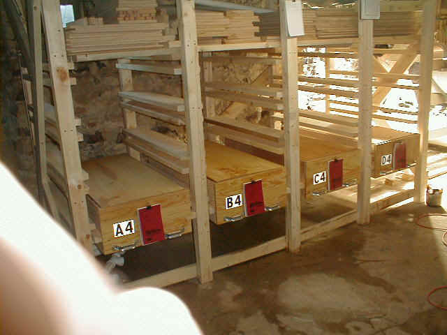
| This is the overall view of the first
four beds and the frame that holds them. Stacked on
top is all the pre-cut components to construct the next
12 beds. Note that each bed is identified by a letter and a number. The letter represents the column (A through D) while the number represents the row (1 through 4) Also note that each bed has it's own Log, where anything affecting that bed is recorded. |
 |
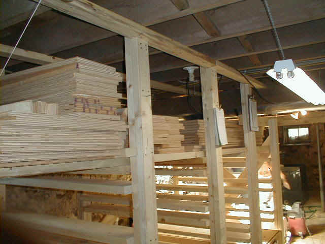
| Here we see more detail of the pre-cut
components of the beds. Note the two additional notebooks. The one mounted on the center is for recording anything that affects all beds equally, such as ambient temperature and relative humidity. The notebook on the next support is for recording everything relating to the hydroponics setup. |
 |
| Here is a close-up of the front of a single bed including it's individual Log. |  |
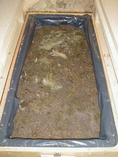
| Here, we see the inside of bed C4, where
an experiment is taking place by mixing the grass
clippings into the soil. A4 and B4 are the baseline where an inch of grass clippings is simply placed on top of the soil. Comparing the productivity of this bed to the control group should give us a better idea of the best way to feed the worms. |
 |
| This photo shows the design for bracing each end of the frame. |  |
| The purpose of this photo is to show how the top slide brace allows the bed to be pulled out to within about 6 inches from the back without falling out. | 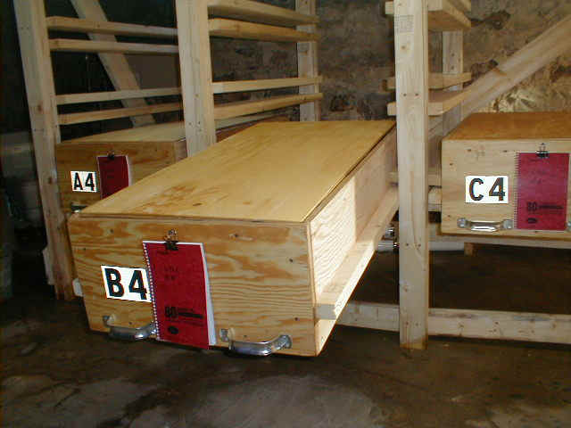 |
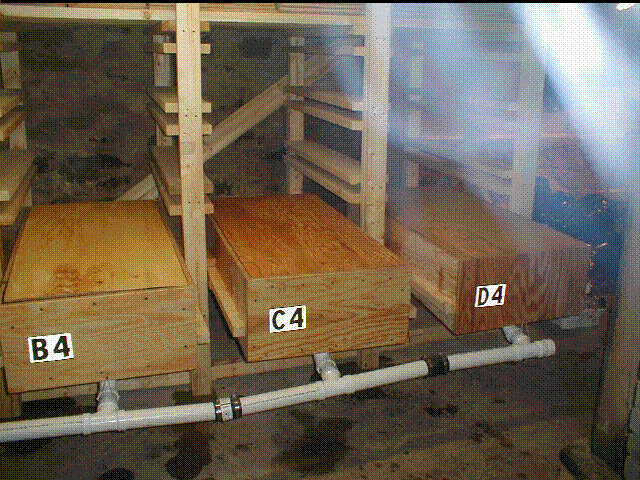
| This photo shows the design of the
plumbing to catch the nutrient rich water after draining
through the beds. Note the flexible rubber joints required because of extreme irregularities in the floor. |
 |
This page was produced by Ron Darby.